


Application
Optical Alignment, Cylinder to Crosshead Guide
Including perpendicular relationship between crosshead centerline and bed section and distance piece flange face mating surfaces.
Equipment
Dresser-Clark 2-CLBA-1 Reciprocating Compressor
History
This machine is one of three similar units originally installed in 1982. They are operated as part of a natural gas reinjection system in a producing oil field. Alignment checks were performed as part of a system upgrade in 2002. New cylinders were being installed to handle larger gas volumes.
This unit has a chronic history of various failures including excessive packing wear, worn cylinder liners and cracked piston rods. Cylinder to crosshead guide alignment checks had previously been performed in 1988 and again on cylinder #1 in 1995, with the old cylinder configuration. Cylinder alignments were documented as exceeding manufacturer’s tolerances, but were not corrected at those times.
2002 Alignment: New cylinder installation was started in March 2002. Alignment data was obtained with standard optical tooling instruments. Cylinder to crosshead guide alignments were measured with an optical line scope. The telescope was mounted on a universal adjusting bracket attached to a custom shelf bracket, which was bolted to the cylinder head. Wire centering targets were installed in the cylinder liner and crosshead guide surfaces. Cylinder targets were held in the 7.500” diameter bore by custom made target holder plugs. These holders were fabricated by the customer using TERN specifications. Crosshead guide targets were mounted in custom built adjustable centering devices supplied by TERN.
The cylinder target plugs are machined to 7.498” diameters. This allows .002” clearance so that they may be slid into the 7.500” diameter cylinder liner. Thus, the center of the target rests .001” below the actual center of the cylinder liner. The optical data has been corrected to account for the cylinder targets being .001” low. Also, all readings are taken with the targets in a 0 degree and 180 degree orientation. This eliminates any error induced by eccentricity between the target plug inside diameter and outside diameter, or between the target wire center and wire target outside diameter. The average of these two readings, which are 180 degrees opposed, is reported as the measured value.
When the cylinders were first bolted into place the alignment was found to be totally unacceptable. Inspection revealed that the cylinder head spigot was coming into contact with the shoulder of the spigot bore. This situation was corrected by cutting a chamfer on the cylinder spigot. While this improved the alignment position of both cylinders, misalignment still exceed manufacturers’ specifications. Further inspection revealed that the cylinder flange face mating surface was not perpendicular to the cylinder liner. One cylinder had a run-out of .0065” and the others runout was .0045” over the bolting circumference. Maximum allowable runout is .002”. This was the first of three units being upgraded. Therefore, there were four other cylinders on-site. The run-out on these other cylinders was checked. Three were found to have runouts of .002’ or less. The best of the lot were installed. Cylinders with excessive runout were sent for re-machining.
After installing the cylinders with acceptable run-outs, misalignment was still outside the manufacturers’ maximum allowable limits. They were however, within the historical range of alignment readings found in 1988 and 1992 with the old style cylinders. Since the cylinders had now been thoroughly inspected the remaining misalignment pointed toward anomalies with the bed sections and/or distance pieces. However, due to the maintenance schedule and production considerations the unit was re-assembled and brought back on-line. It was decided that this machines alignment would be re-visited once the cylinder upgrades were completed on the other two machines. In the meantime, and in anticipation of possibly finding a mis-machined bed section or distance piece, a spare bed section and distance piece were located and expedited to the site.
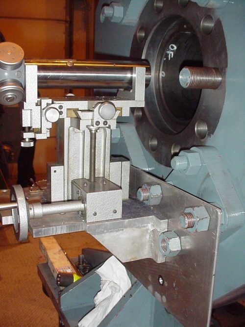
The following photographs illustrate the optical line scope and target set-up used for this alignment check. The connecting rods were removed exposing the whole crosshead guide for measurement.
Picture One, Optical Line Scope Mounted on Cylinder
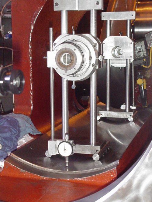
Picture Two, Adjustable target holders installed in crosshead guide
Alignment work commenced again in June 2002. Prior to cylinder installation the alignment relationship between the distance pieces and bed sections was verified. Data showed excessive misalignment. Next, the flange face mating surfaces of the bed sections were checked to verify their perpendicular relationship to the crosshead guide centerline. The #1 bed section was found to be out of square by .011” over the bolting diameter. The #2 bed section was found to be out of square by .006”.
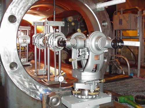
The following photograph illustrates the optical set-up used to measure the perpendicularity of the flange face mating surfaces. In this application a special optical transit square with a focusable cross scope is used. This instrument is actually two telescopes built together such that they are at right angles to each other. With the transit adjusted to the centerline of the working piece, the cross scope is used to measure optical scales held on the flange face being measured. If the flange face is perpendicular to the crosshead guide centerline, all scale readings obtained would be equal. Unequal readings indicate the amount and direction which the flange face is out of square relative to the crosshead guide. The same adjustable target holders used to measure cylinder alignments are used to establish the center of the crosshead guide.
Picture Three, Cross Scope set-up on bed section
Note: Optical scales on upper right side of flange face and adjustable optical targets in background.
A similar set-up was used to measure the distance pieces. Distance pieces were removed from the machine and measured in the shop. The distance pieces were found to be true with runouts at both ends within .002”.
While one spare bed section and distance piece combination was available for installation it was not used. Instead, the existing bed sections were field machined in place. A flange face cutting tool was mounted centered to the crosshead guide centerline and the flange face was skim cut to make it truly perpendicular. Before and after optical data is shown below.
THROW #1 THROW #2
As-Left As-Left
As-Found After Machining As-Found After Machining
0 Degrees N/A N/A N/A N/A
45 Degrees 9.479” 9.4985” 9.508” 9.471”
90 Degrees 9.480” 9.4995” 9.511” 9.471”
135 Degrees 9.4825” 9.499” 9.514” 9.4725”
180 Degrees N/A N/A N/A N/A
225 Degrees 9.490” 9.499” 9.5125” 9.471”
270 Degrees 9.488” 9.4995” 9.511” 9.473”
315 Degrees 9.485” 9.499” 9.5095” 9.473
Maximum Deviation .011” .001” .006” .002”
Picture Four, Flange face cutter on bed section
Cylinder Alignment Data: Data below expresses the cylinder centerline position relative to the crosshead guide centerline. Left (L) and right (R) is as viewed from the line scope location on the cylinder end looking toward the crosshead guide.
Reference Reference Vertical Horizontal
Crosshead Crosshead Cylinder Cylinder Cylinder Cylinder
Crank End Cyl. End Inner Outer
1988, Cylinder #1 .000” .000” -.0165” -.018” R .004” R .004”
1988, Cylinder #2 .000” .000” -.011” -.0145” R .0085” R.0085”
1995, Cylinder #1 .000” .000” +.0275” +.0305” L .004” L .006”
1995, Cylinder #2 . Data Not Recorded
2002, Cylinder #1 .000” .000” -.001” -.0035” R .002” R .0025”
2002, Cylinder #2 .000” .000” -.0095” -.0095” L .0075” L .010”
The following alignment drawings show the 2002 final alignment position of the new cylinders.