


Application
Piping Movement Survey using Permalign® Laser Measurement System
Equipment
Dresser-Clark Hot Gas Expander (Turbine), 60-inch Inlet Flange
History
Piping support modifications and piping replacements were being made as part of activities during an oil refinery turn-around. Similar modifications on a like unit at a “sister” refinery had resulted in major turbine casing rotor rubs. This caused major damage and prevented post-turnaround refinery start-up. The monitoring program was designed to insure that, in this instance, the inlet flange would not be moved so as to distort the turbine casing and cause a similar damage and shut-down. Movement was also monitored during piping dis-connect. This was simply to catalog what piping stresses the turbine casing was under prior to modifications. A “static” testing period was also added to show the normal amount of movement occurring that is unrelated to piping activity. Most of this movement is thought to be caused by ambient temperature fluctuations and changing sun position throughout the testing period.
Project description
A Permalign® monitoring system was used to collect movement data on the turbine inlet flange. A total of three laser monitors were used to measure movement in the vertical, horizontal and axial planes. Permalign® is a laser sourced measuring system. It senses relative movement of a prism and detector across distances of zero to thirty-three feet. By employing a reflected beam measuring principle, thermal and vibration stability are achieved. System resolution and repeatability are one micron with a maximum error of less than 2% of the displayed value. The high resolution, repeatability, and accuracy are due to the use of a linearized photo detector in the design.
Permalign® monitors may be fixed to the foundation or other positions of interest to reveal displacements or angles of those points along the horizontal (X) and vertical (Y) axis of the monitor. Standard Cartesian coordinate conventions apply to Permalign( monitors and are defined as if looking into the lens of the monitor. Hence, with the monitor oriented in a normal upright position, the X-axis is lateral data (horizontal or axial) and the Y-axis is vertical data.
For the purposes or this study, 90û roof prism reflectors were used. In other applications triple prisms may be used. Triple prisms respond to displacement movement along both axes and not to angular deviations. The 90û roof prism responds to displacement along the Y-axis and angular deviation along the X-axis.
The Permalign® laser system is used in conjunction with application software, Winperma®. Data is collected in spreadsheet and graphical formats. Winperma® allows the user to set the polling frequency for each monitor for measuring changes in displacement over time. Monitors were connected to a PC for the purposes of data collection. Winperma® was configured to poll data from the monitors every minute during piping disconnect and 15 seconds during piping re-connect activities. Following each poll, Winperma® averages and plots displacement information received from the biaxial detector.
Monitors were mounted to the turbine deck and I-beam supports. The movement recorded is relative to each monitor attachment point.
It is essential to understand machine and monitor orientation to properly interpret the Permalign® data. The machine centerline is said to run on a north/south axis, with the turbine inlet on the north end. The following photographs are provided to help illustrate the position and relationship of the various monitors and prisms. A total of three monitor/prism pairs were used for this study. Monitor #7 was mounted to a bracket support bolted to an I-Beam on the east side of the unit. Monitor #7 orientation is such that the Y-axis records horizontal displacement along the machine east-west axis. Angular deviation or rotation about the machine east/west axis is recorded on this monitors X-axis. Monitors #0 and #9 were mounted on a pipe stand support bolted to the west side of the turbine skid. Monitor #0 orientation was such that it recorded vertical displacement on the Y-axis. The X-axis recorded angular deviation or rotation about the vertical axis. Monitor #9 recorded axial displacement on the Y-axis. The monitor X-axis recorded angular deviation or rotation about the machine north/south axial axis.
Sample Winperma( graphs of displacement vs. time are shown below. All Y-axis data is shown in black (offset displacement). All X-axis data is graphed in “red” (orange) and is displacement representing angular rotation about the X-axis. Graphed Y-axis data is the actual displacement value recorded. The graphed X-axis value is the raw displacement value converted to an angular value expressed in mils per 60 inches (inlet piping flange diameter).
Monitor orientation is detailed below. Following this explanation photographs are provided to help further illustrate the laser installation and orientation.
Monitor #7, East Side, Horizontal and Axial Displacement
Monitor Orientation: The vertical Y-axis is oriented along the machine east/west axis such that it records horizontal offset values. Plus (+) is movement toward the east and minus (-) is toward the west. Therefore the horizontal X-axis is oriented so that (+) is up and (-) is down. This axis shows displacement representing rotation about the east/west machine axis. Plus (+) values indicate rotation such that the bottom of the flange moves toward the north (toward the inlet) and the top moves to the south (toward the expander).
Monitors #0, West Side, Vertical and Axial Displacement
Monitor Orientation: The vertical Y-axis is oriented in the normal upright position such that (+) is up and (-) is down. It records vertical offset values on the west side of the flange. The horizontal X-axis is aligned along the north/south axial axis such that (+) is toward the north, or away from the expander, and (-) is toward the south, or toward the expander. The vertical Y-axis shows vertical offset. The horizontal X-axis shows horizontal angular change, or rotation about the vertical Y-axis. Plus (+) values indicate rotation with the west side of the flange moving toward the north, or away from the expander and the east side of the flange moving toward the expander, or south.
Monitors #9, East Side, Axial and Vertical Displacement
Monitor Orientation
The vertical Y-axis is oriented along the machine north/south axial axis such that it records axial offset values on the west side for the flange. Plus (+) values represent movement toward the expander, or south, and minus (-) movement is away from the expander, or north. Therefore, the horizontal X-axis is oriented so that (+) is up and (-) is down. This axis shows vertical angular displacement or rotation about the machine north/south. Plus (+) values indicate rotation with the west side of the flange moving up relative to the east side of the flange. Minus (-) values show rotation in the opposite direction.
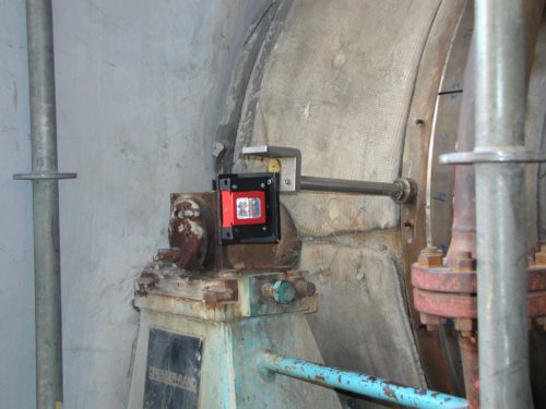
Photograph #1
Prism #7, Monitors Horizontal Offset and Rotation about the east/west machine axis.
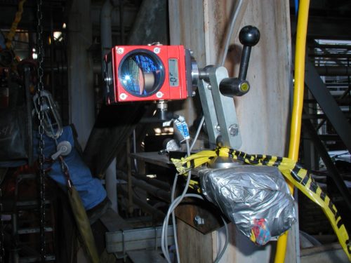
Photograph #2
Monitor #7, Records Horizontal Offset and Rotation about the east/west machine axis.
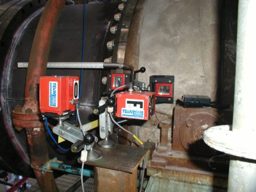
Photograph #3
Monitor/Prisms #0 and #9
Monitor #0 Records Vertical Offset and Rotation about the machine vertical axis.
Monitor #9 Records Axial Offset and Rotation about the north/south machine axis.
Note: Monitor #9 is labeled #F in this photograph
Permalign® Data Overview
A significant amount of movement was observed during piping disconnect. It was also observed that the inlet piping moved away from the expander inlet flange at unbolting. This movement was in excess of one inch, and indicated that there was a significant amount of cold pipe stress on the expander inlet flange. The largest movement observed is in the axial angle position of the flange. This value was .0563”/60” diameter. This may be because this is the easiest direction in which to influence flange position, or it may be that this was the direction of the greatest amount of existing pipe strain.
The most significant factor revealed during the static test on November 6, 2002 was the rapid progressive change in the horizontal offset reading at Monitor #7 between approximately 9:00 am and 11:30 am. Observed movement during this period was approximately .020”. Fluctuations in this position after 11:30 am were less than .010”. However, since pipe bolting and un-bolting activities occurred after 11:30 am the movement that occurred in the morning hours did not severely affect the interpretation of the movement caused by piping activity.
Very little expander flange movement was observed while attaching the new piping. Since this was the desired effect, the monitoring showed a successful outcome. Offset value changes, vertical, horizontal and axial, were each under .002”. They were -.0004”, -.0012” and -.0004” respectively. Angular value changes were each under .011” when expressed over a 60” diameter. This is approximately .002” per foot. Angle values were +.0016”/60”, -.0106”/60” and +.0036”/60” for axial, vertical and horizontal respectively. Also, the static test showed that as much as .0032” of the vertical angle rotation could be the result of normal fluctuation, and not the result of movement caused by piping activity. So the reported vertical angle of -.0106” can be interpreted as really being less, or -.0074”.